Introduction
A crane incident is rarely just a crane problem. The equipment may be the center of attention, but the surrounding site often matters just as much. Ground conditions, support points, nearby structures, access routes, overhead utilities, the load area, temporary work features, and the position of other equipment can all become part of the technical review.
That is where ordinary photography can come up short. A close photograph can show a damaged component in excellent detail while giving very little sense of where it was located within the larger work area. Once equipment is moved, debris is cleared, or the site returns to normal operations, that missing context can be difficult to rebuild.
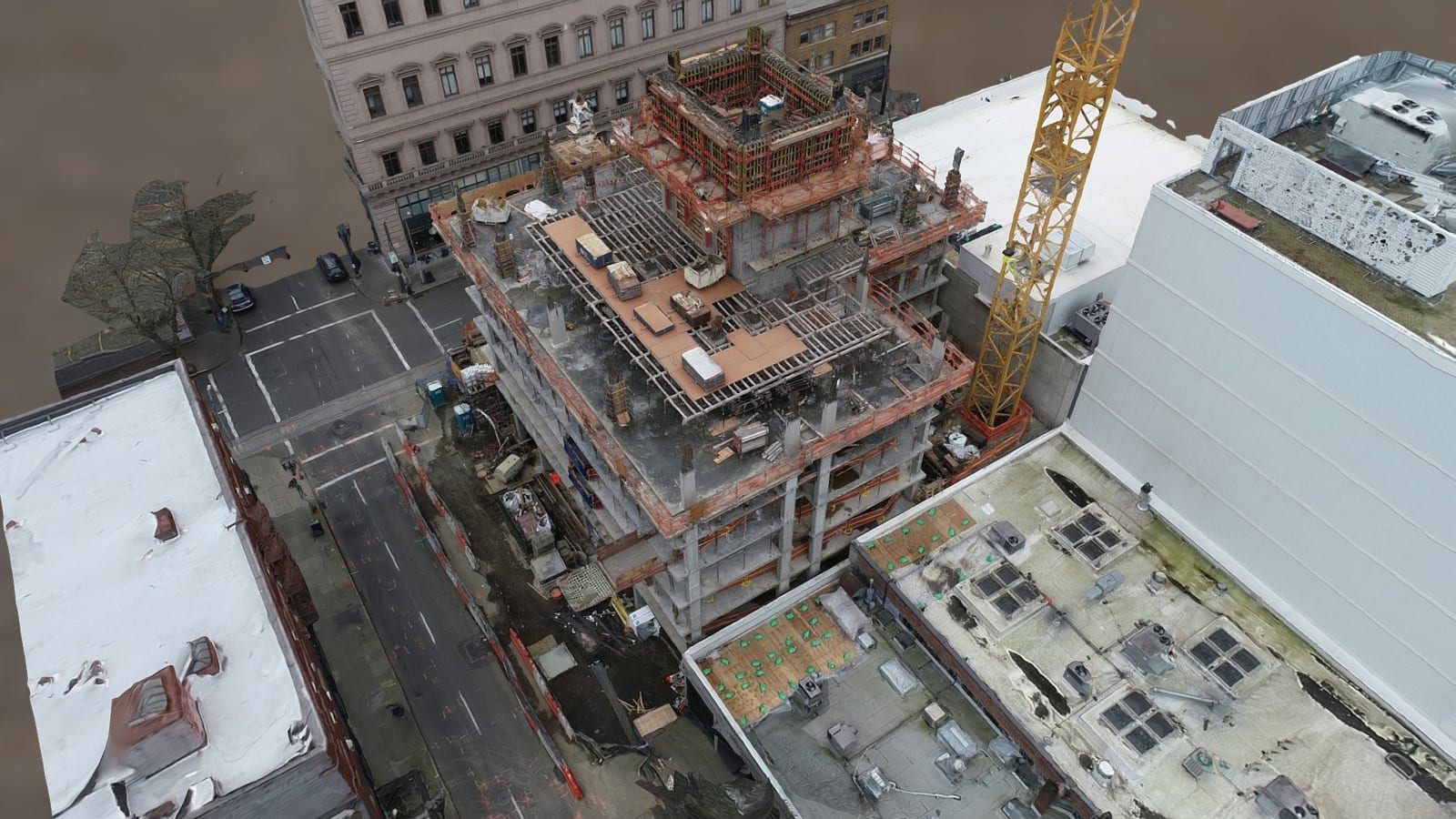
Reality capture gives the field team another way to preserve the scene. Aerial imagery, ground photography, photogrammetry, point clouds, terrestrial capture, measurements, and annotated views can be used together when the project calls for them. The point is not to use a 3D model to decide why an incident happened. The point is to preserve what was physically there so the right expert has more to review later.
For crane and rigging work, that distinction is important. Technical conclusions about crane setup, rigging, ground support, operating practices, OSHA requirements, engineering, or causation belong with the qualified professionals responsible for that analysis. The documentation should give them a better record to work from.
Why crane incident scenes are hard to document
The working area around a crane can cover far more space than the damaged equipment itself. Depending on the project, the scene may include the carrier or crawler base, outriggers, mats, cribbing, counterweights, boom position, rigging, a suspended or dropped load, nearby structures, slopes, trenches, utility lines, laydown areas, access roads, barricades, and other equipment.
Traditional photographs are still essential. They preserve surface detail, labels, connection points, damage, and viewpoints that a model may not capture well. The problem is that photographs are normally collected as separate frames. A reviewer who was not at the site may later have to work out where each image was taken and how one feature relates to another.
OSHA incident investigation guidance recommends documenting the scene promptly with photographs or video, measurements, and the location of important evidence because conditions can change. Reality capture fits into that same field documentation process. It does not replace basic scene photography or measurements. It gives those records more spatial context.
Start with the entire work area
After a serious equipment incident, it is natural to focus on what looks damaged. A collapsed boom, failed rigging component, overturned crane, or dropped load will immediately draw attention. Those details need to be documented, but starting too close can leave out the part of the scene that explains where everything sat in relation to everything else.
A useful record starts wide. The first pass should establish the crane and work area within the larger site. That may include the structure involved in the lift, access roads, staging areas, adjacent equipment, excavations, slopes, overhead lines, property limits, and the areas used to set up or move equipment.
Aerial imagery is useful here because it can show relationships that are difficult to see from ground level. When the site and flight conditions allow it, overlapping images can be processed into an orthomosaic or 3D model. Ground photography then fills in the details that cannot be seen from above.
Crane setup and support conditions
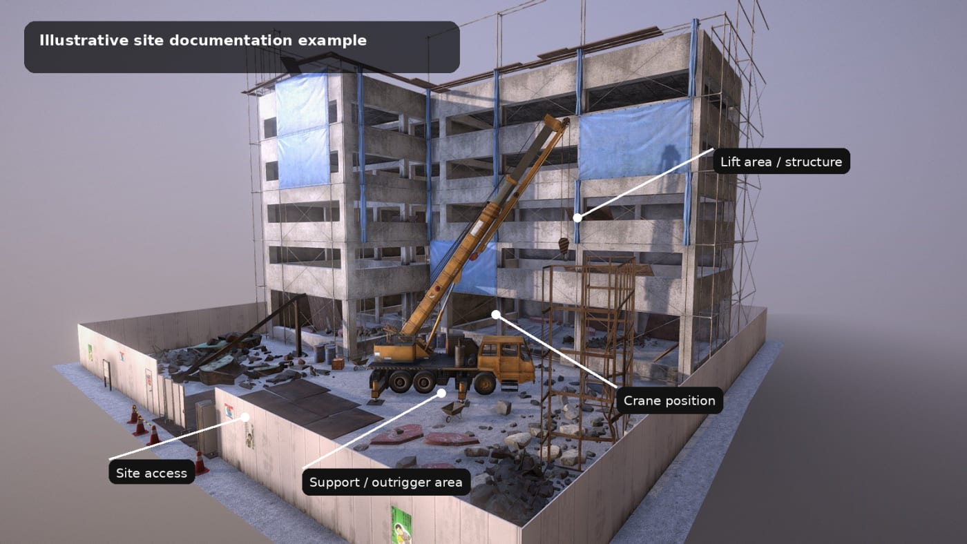
The relationship between the crane and the surface supporting it deserves its own documentation. OSHA 29 CFR 1926.1402 addresses ground conditions for cranes in construction, including the ability of the ground to support the equipment and the use of supporting materials such as mats, blocking, and cribbing.
A documentation technician should not turn those observations into a compliance or causation opinion unless that person is qualified and retained to do so. What can be done is to preserve the visible condition of the support area before it changes.
Depending on the scene, the field record may include:
- overall crane position and orientation
- outrigger or crawler locations
- visible mats, cribbing, blocking, or other support materials
- ground surface around each support point
- visible slopes or grade changes
- nearby trenches, excavations, voids, or disturbed soil
- standing water or visible drainage conditions
- the relationship between the crane and nearby structures or work areas
Work zone geometry and nearby hazards
The work zone can change quickly after an incident. Equipment may be recovered, loads removed, barricades moved, damaged material cleared, and access restored. A mapped site record can preserve the visible arrangement before those changes happen.
That can be useful when a reviewer needs to understand distances and relationships later, such as the crane location relative to a structure, the apparent location of a load, the space available around the equipment, or the position of temporary site features.
Power line proximity is one example. OSHA 29 CFR 1926.1408 requires employers to identify the work zone and evaluate whether equipment, load lines, loads, rigging, or lifting accessories could approach power lines within specified distances. A reality capture model does not make that regulatory determination. It can preserve the visible location of the equipment, work area, and overhead utilities when those features can be documented safely.
Document the load area, not just the final position
A crane incident may raise questions about where a load started, where it was intended to go, what was between those locations, and how the site limited movement. Those are questions for the technical team. They are also a reason to capture more than the final resting position of the crane or load.
When visible and within the approved scope, useful documentation may include the load location, staging area, destination area, nearby structures, obstructions, travel paths, access limitations, and the larger area around the lift. Seeing those features together can make the site easier to understand than reviewing a folder of unrelated photographs.
Aerial and ground capture should work together
No single capture method sees everything. A drone can show the overall site but may not clearly document areas beneath equipment, labels, connection points, rigging details, or surfaces blocked by structures. Ground photography can capture those details but may not explain where each photograph belongs within the larger scene.
For that reason, the capture plan should be built around the questions the project may need to answer later. Aerial photogrammetry can establish site layout. Ground photography can preserve details and surface conditions. Terrestrial reality capture can help with complex areas at closer range. Conventional field measurements may still be the right choice for critical dimensions.
The useful part is being able to move from the wide view down to the detail. A reviewer can first see the overall work area, then the crane support area, then the specific photograph or measurement tied to a particular feature.
What the documentation package may include
Not every scene needs every deliverable. A large outdoor site may benefit from aerial mapping, while a compact industrial setting may depend more on ground based photography and terrestrial capture. The scope should be decided before field work when possible.
A crane incident documentation package may include:
- an orthomosaic for overall site orientation
- a 3D model or point cloud for spatial review
- high resolution aerial and ground photographs
- close imagery of equipment, support points, rigging, and surrounding surfaces
- annotated site views identifying documented locations
- selected measurements when the capture was planned for measurement
- 360 imagery or terrestrial reality capture, such as Matterport, when moving through the site helps explain the layout
- original source files and organized supporting records
- capture dates, file naming, and processing notes
Measurements need to be planned
A 3D model is not automatically a precision measurement record. Measurement quality depends on the capture method, camera geometry, sensor, control, surface visibility, processing, and site conditions. A model can look convincing and still contain areas that are poorly reconstructed or not suitable for a critical measurement.
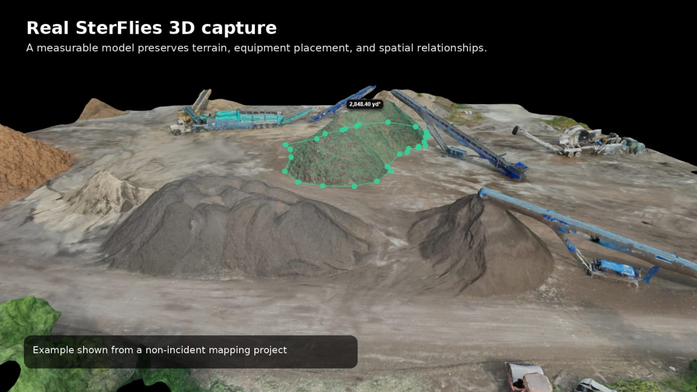
If distances between crane supports, equipment, structures, or other important features may matter later, that requirement should be known before the field work begins. The project can then be captured and controlled with that use in mind instead of assuming every measurement can be recovered after the fact.
Photogrammetry also does not replace a licensed survey when a legal survey or survey grade control is required. The final documentation should clearly state what method was used and avoid claiming more accuracy than the project supports.
Keep documentation separate from conclusions
The field record should describe what was captured, where it was captured, when it was captured, and how the deliverable was produced. It should not turn visible conditions into a theory of the incident.
For example, a site record can identify an outrigger location, a measured distance, a visible slope, or the position of an overhead line. It should not state that the ground caused an overturn, that a rigging configuration was improper, that an OSHA requirement was violated, or that an operator acted incorrectly unless those conclusions come from the qualified professional responsible for that analysis.
Keeping those roles separate matters when the same record may be reviewed by safety professionals, attorneys, engineers, insurers, expert witnesses, and other consultants. Each person can evaluate the same physical record within the scope of their own work.
Connecting field documentation to technical review
Spear & Lancaster works in crane and rigging safety, incident investigation, construction safety, OSHA related matters, root cause analysis, and expert witness support. SterFlies can add another layer to the field side of that work by preserving the site in a form that can be reviewed after the initial visit is over.
The expert still owns the interpretation. The documentation simply gives that expert more context than a loose collection of photographs and notes may provide. Depending on the project, that can mean a focused ground based record, a complete aerial map, a 3D model, or a combination of several methods.
This also makes the field response easier to plan. When a client contacts Spear & Lancaster after a serious incident, the technical team can decide early what needs to be documented before equipment is moved or site conditions change.
A practical field workflow
A crane and rigging incident documentation workflow can be kept straightforward:
- Secure access and coordinate with the responsible site parties before capture begins.
- Define the documentation objective with the professionals who will review the record.
- Capture the overall site before focusing on individual components.
- Document the crane position, support areas, surrounding ground, load area, nearby structures, utilities, and access conditions that are visible and relevant to the scope.
- Collect close photographs and ground level context for details aerial capture cannot preserve.
- Collect critical field measurements or control information when later measurement is part of the objective.
- Process only the deliverables the project actually needs and retain the original source files.
- Organize the record so a later reviewer can determine what was captured, where it was captured, and when it was captured.
- Provide the documentation to the qualified professionals responsible for technical analysis and conclusions.
Conclusion
Crane and rigging incidents involve more than a single piece of equipment. The crane, support conditions, load, rigging, structures, utilities, terrain, access, and surrounding work area all exist in relation to one another. If the scene is documented only through isolated photographs, some of those relationships may be difficult to recover after the site changes.
Aerial mapping, ground photography, 3D models, point clouds, terrestrial capture, and conventional measurements can preserve different parts of the same scene. Used together and planned around the project, they can leave the technical team with a clearer record of what was physically present.
That is the role SterFlies can fill. Preserve the site carefully, organize the record, and leave the technical conclusions to the professionals responsible for making them.