
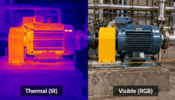
A thermal image of an industrial pump can be convincing. One bearing housing appears bright orange, while the surrounding machinery is blue and purple. To someone reviewing the image without context, the conclusion may seem obvious: that component is overheating. But what was the pump doing when the image was taken? Was the camera comparing painted metal with bare steel? And does the color scale reflect a large temperature difference or a narrow range chosen by the operator?
Those questions matter because infrared imaging does not directly photograph a mechanical defect. It records radiation reaching the sensor and, when the equipment and settings allow, estimates apparent surface temperature. An unusual pattern may indicate an area worth examining. It does not explain why the pattern occurred.
Industrial investigations often involve equipment conditions, heat transfer, operating histories, and the physical arrangement of a work area. Thermal documentation can preserve information about those conditions, especially when paired with conventional photographs and an accurate record of the inspection. Its usefulness depends on understanding both the image and the method’s limitations.
The Difference Between a Thermal Pattern and a Temperature Measurement
The colors in a thermal image are a visual representation of infrared data, not the natural colors emitted by the object. A camera may display warm regions as yellow or white and cooler regions as blue or black, but the palette can usually be changed without altering the underlying measurement. More importantly, the displayed temperature range can be narrowed or widened.
Imagine a camera view spanning 20°C to 120°C. A small difference between neighboring surfaces may be hard to see. Narrow the display to 35°C to 45°C, and those same surfaces can look dramatically different. FLIR explains that level and span adjustments affect image contrast and can make patterns easier to examine; they do not, by themselves, validate a defect (FLIR, “Achieving a Good Thermal Image”).
A thermogram used for technical review should retain its temperature scale and measurement context. When comparing two images, the reviewer needs to know whether their scales and camera settings are comparable. A picture without a scale, location information, or original data may be useful as an illustration but is a weak basis for a quantitative statement.
Even a numerical temperature displayed on the screen needs qualification. The camera estimates surface temperature from radiation, which also depends on material properties and the surrounding environment. The number should not be treated as equivalent to a calibrated contact measurement in every circumstance.
Why Polished Metal Can Appear Hot When It Is Not
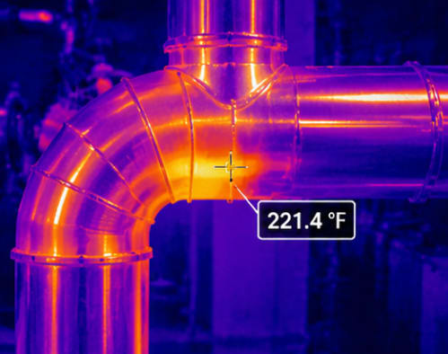
Industrial facilities contain many surfaces that are difficult to assess with infrared cameras: stainless-steel tanks, polished pipes, electrical enclosures, and exposed metal components. A clean, shiny surface may reflect infrared radiation from nearby equipment, lights, the operator, or other surroundings.
The relevant material property is emissivity, which measures how effectively a surface emits thermal radiation relative to an ideal blackbody at the same temperature. Low-emissivity surfaces often reflect a larger share of the radiation the camera receives. FLIR describes emissivity and reflected apparent temperature as important factors in interpreting measurements, particularly for polished metals (FLIR, “How Does Emissivity Affect Thermal Imaging?”).
For example, a reflective pipe may show a bright patch that shifts as the camera angle changes. That is an observation worth investigating, not immediate proof that the pipe itself contains a localized hot spot. Repeating the image from a different safe viewing position can help reveal a reflection. When accurate temperatures are required, qualified thermographers may use appropriate reference surfaces and compensation procedures rather than relying on default emissivity settings.
Glass presents a related limitation. Ordinary window glass typically blocks the long-wave infrared radiation used by many industrial thermal cameras, so the camera may record the window surface and reflections rather than the equipment behind it (FLIR, “Can Thermal Imaging See Through Walls?”).
Operating Conditions Are Part of the Evidence
A motor under full load may exhibit a different temperature pattern than the same motor during startup or after shutdown. This difference may be expected. Fans, pumps, conveyors, switchgear, and electrical distribution equipment should be considered in the operating state in which they were observed.
Comparing unlike conditions can lead to misleading interpretations. A thermogram of an energized electrical component cannot be automatically compared with one taken after the load was removed. Likewise, an exterior tank warmed by afternoon sunlight is not directly comparable to a morning image taken before the sun reached the surface.
Useful field notes document the operating status when known, along with approximate load or process conditions from qualified site personnel. Ambient temperature, wind, direct solar exposure, recent rain, and the time since equipment was turned on or off may also matter. Recording these details takes little time compared with the effort required to interpret an unexplained temperature pattern weeks later.
When a component appears unusual, comparisons with similar components can be informative only if their materials, functions, loadings, and surroundings are sufficiently comparable. The aim is to establish a meaningful comparison, not to eliminate every temperature difference.
What a Hot Spot May Suggest and What It Cannot Prove
Thermal imagery can reveal localized apparent temperature differences on bearings, motor housings, power connections, insulation surfaces, ductwork, and process piping. These patterns may help identify equipment that warrants closer examination, especially when other records already point to the same location.
Yet a hot area does not uniquely identify an underlying cause. Friction, electrical resistance, nearby heat sources, process flow, surface finish, and reflected radiation may produce patterns that look similar. A thermal image cannot, from appearance alone, establish that a bearing was improperly lubricated, a connection was loose, or an electrical component was overloaded.
The same restraint applies to areas that appear unusually cool. Cooling may result from airflow, evaporation, insulation, process conditions, or environmental exposure. A cooler region cannot be labeled a leak or moisture intrusion based solely on its thermal appearance.
The next step depends on the question under investigation. Qualified maintenance personnel, engineers, or other specialists may need additional photographs, equipment records, contact temperature measurements, electrical testing, or direct inspection. Thermal documentation can help guide that work. It is not a substitute for it.
Electrical Equipment Requires Its Own Safety Boundaries
Electrical thermography can be valuable because many components change temperature when energized and under load. However, it also raises serious safety considerations. Opening an electrical enclosure or approaching exposed energized parts is not justified merely because a thermal photograph would be useful.
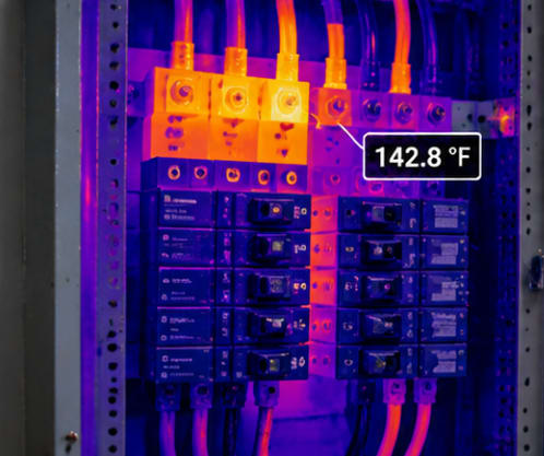
OSHA requires safety-related work practices when employees work near or on equipment that is or may be energized. Its general industry electrical rules restrict work on energized circuit parts to qualified persons who are familiar with the necessary precautions and protective equipment (Occupational Safety and Health Administration, “1910.333”).
The documentation team should coordinate with the facility’s qualified electrical personnel. The scope may need to be limited to closed-panel exterior imagery or other safe viewpoints. If a specialized inspection requires access to energized components, the responsible qualified personnel must determine the appropriate procedure. A thermal camera does not eliminate shock or arc-flash hazards.
This division of responsibility matters in an investigation. The image collector can record the apparent surface-temperature pattern, camera position, timestamp, and accessible equipment labels. Electrical condition, code compliance, and failure mechanism remain questions for properly qualified reviewers.
Distance, Target Size, and the Risk of Misreading a Small Component
It is tempting to zoom in on a thermal image after capture to read the temperature of a very small feature. But a small fastener or connector may occupy only a fraction of the camera’s effective measurement area. Its displayed value can then be influenced by neighboring surfaces.
Camera resolution, lens characteristics, focus, and distance all determine whether a target is large enough for a useful temperature measurement. FLIR’s imaging guidance cautions that an operator must consider the sensor’s resolution limit and the size of the observed object, not merely whether the feature is visible on a screen (FLIR, “Achieving a Good Thermal Image”).
The practical response is to plan safe vantage points and appropriate optics for the object that matters. Moving closer may improve the result, but only when access and site hazards permit. A digital enlargement cannot recover temperature information the sensor never resolved.
A thermal image can also be limited by what is in front of the target. Walls, metal cladding, and many other opaque materials cannot be seen through by an ordinary long-wave infrared camera. The camera records the visible surface, not a direct image of a concealed component behind it.
The Value of Recording the Same Equipment in Visible Light
One frequent problem with thermal documentation is not the thermal image itself, but rather finding the subject again. A cluster of glowing shapes may be recognizable to the operator standing beside the machine. Months later, another reviewer may not know which motor, valve, or panel was photographed.
For each significant thermal image, a corresponding conventional photograph helps identify the equipment, surrounding structures, direction of view, and nearby reference points. A wider context photograph can be particularly useful when several similar machines are in the same area.
When appropriate, an annotated site photograph or a 3D facility record can link the observation to a physical location. The annotation should describe what was recorded, not assert a diagnosis: “Thermal image T04, south motor housing, captured during operation” is more defensible than “failed bearing” when a mechanical examination has not established the condition.
This approach aligns with the broader purpose of SterFlies’ documentation work. Thermal imaging can be one component of a record that includes ground photography, equipment identifiers, and spatial context. Its value increases when a qualified reviewer can precisely determine where the image was taken and what conditions were present.
Preserving Radiometric Data and the Conditions of Capture
A colorized image exported as a flat JPG may not retain the underlying temperature information needed for later adjustment or review. Some thermal cameras can save radiometric files that preserve calibrated sensor data and associated parameters; the exact capabilities depend on the camera, file format, and software.
When temperature analysis is part of the assignment, the original radiometric files should be retained alongside any derived images. A basic documentation package may also include the capture date and time, camera and lens information, emissivity and reflected-temperature settings (when used), distance or range estimates, the selected palette and temperature scale, and relevant site conditions.
The record should distinguish between values actually measured or entered in the field and assumptions used later in processing. If a parameter is unknown, it is better to state this than to create the appearance of precision after the fact.
File names and location references also matter. A sensible numbering convention can link thermal frames to visible-light photographs and to a field log. This allows the reviewer to trace an observation to its source without guessing which image corresponds to which piece of equipment.
A Practical Example: A Warm Pump Housing
Consider a hypothetical investigation at a processing facility where a pump housing appears warmer than the surrounding machinery. A technician captures a thermal image, a corresponding conventional photograph, and a wide view that shows the pump’s position in the room.
The image alone raises questions. Was the pump operating under the same load as its neighbor? Are the surfaces painted the same? Was a heated process line nearby? Is the apparent hot area still visible from a different viewing angle? Could the camera’s measurement spot include multiple surfaces?
The documentation team records the conditions it can verify and refers technical questions to the relevant specialists. A maintenance engineer might review operating records, temperatures at designated reference locations, vibration history, and component condition. Those findings may or may not support the initial concern.
This scenario illustrates the appropriate role of thermal imagery: it preserves a time-specific observation that can be tested against other information. The photograph is not proof of a failure mechanism, and its usefulness should not hinge on treating it as such.
Writing Findings That the Image Actually Supports
Good thermal reporting separates three elements: the observed pattern, the circumstances of capture, and any interpretation offered by a qualified professional. For example, the first can state that the upper portion of an enclosure appeared warmer than adjacent surfaces in a radiometric image. The second can describe load conditions and camera parameters. A conclusion about an electrical fault requires additional support.
Reports should avoid unsupported superlatives such as “severe overheating” when the measurement basis is unclear. If a measured temperature is reported, the method and uncertainty should be clearly stated. If only a qualitative difference can be supported, the report should state that.
What makes thermal imaging valuable in industrial documentation is its ability to capture patterns that ordinary photography may not reveal. That information can help direct attention, provide context for technical specialists, or preserve an observation of a condition that later changes.
Its limits are part of the record, not an inconvenience to hide. A careful thermal image, paired with visible photography and reliable field notes, gives investigators something to evaluate. A dramatic color picture without context gives them much less.
Works Cited
FLIR. “Achieving a Good Thermal Image.” FLIR Documentation. https://docs.flir.com/T810664/en-US/latest/d1010329e1132.html.
FLIR. “Can Thermal Imaging See Through Walls? And Other Common Questions.” FLIR, 4 Oct. 2019. https://www.flir.com/discover/home-outdoor/can-thermal-imaging-see-through-walls/.
FLIR. “How Does Emissivity Affect Thermal Imaging?” FLIR. https://www.flir.com/discover/professional-tools/how-does-emissivity-affect-thermal-imaging/.
Occupational Safety and Health Administration. “1910.333: Selection and Use of Work Practices.” U.S. Department of Labor. https://www.osha.gov/laws-regs/regulations/standardnumber/1910/1910.333.
SterFlies. “Thermal Documentation.” SterFlies. https://sterflies.com/thermal/Applications.